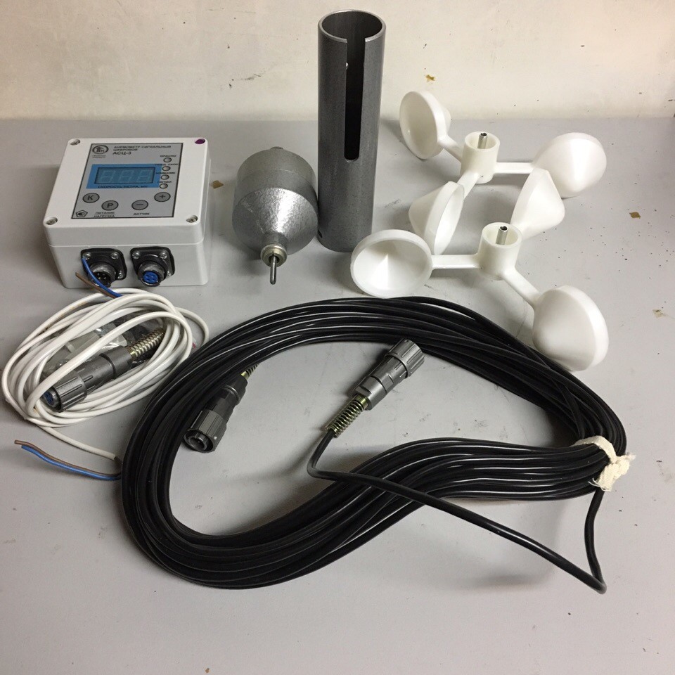
ANEMOMETER ASTs-3
Purpose of the anemometer. 1.1. Anemometer digital signal ASTs-3 is designed to measure the speed of air flow (wind) in an industrial environment, to highlight dangerous wind gusts and turn on signaling devices. 1.2. The anemometer is designed for installation on existing types of tower, gantry, gantry cranes and other objects that require equipment with emergency wind protection devices. 1.3. The use of ASTs-3 is regulated by: - PB 10-382-00 “Rules for the construction and safe operation of cranes”; - GOST 1451-77 “Hoisting cranes. Wind load. Norms and methods of determination ”. 1.4. The wind sensor is designed to be installed in an open place of a crane so that the serviced object does not create a wind “shadow” for the sensor. The control unit is installed in the cabin of the lifting mechanism. 2. TECHNICAL CHARACTERISTICS. 2.1. Wind speed measurement range from 10 to 32 m / s. Wind speed indication range from 3.0 to 10 m / s. 2.2. The setting range for the formation of signals for switching on of signaling devices at the limiting wind speed Vpr should be from 10 to 32 m / s. 2.3. The discreteness of the settings for the formation of signals for switching on of signaling devices is not more than 0.1 m / s. 2.4. The limit of the permissible error of measurement and formation of the control signal for the limiting wind speed Vpr is not more than ± (0.5 + 0.05V) m / s, where V is the measured speed. 2.5. The control unit provides digital indication of the wind speed with a readout resolution of 0.1 m / s. Number of reading characters 3. 2.6. There is a built-in light and sound signaling of the “ATTENTION”, “LIMIT SPEED” and “DANGER” thresholds. 2.7. The anemometer provides built-in monitoring of the Vpr setpoint value and alarm operation. 2.8. When the wind speed exceeds the limit value of 90% of Vpr, the “ATTENTION”, “LIMIT SPEED” signals are switched on and an intermittent sound signal sounds. When the wind speed exceeds the limit value Vpr, after the delay time necessary to cut off short-term gusts, the signal “DANGER” is generated, a continuous sound signal sounds and the relay contacts are closed. 2.9. The delay time for the “DANGER” signal for operation is adjustable from 0 to 10 seconds. Discreteness of changes is 1 second. 2.10. The permissible current in an external load should not exceed: - 2 A when powered from an alternating current network with a voltage of up to 380 V; - 3 when powered from a DC network with a voltage of up to 30 V. 2.11. Non-volatile memory stores the calibration characteristic of the wind speed, the delay time for the signal “DANGER” and the setting of the maximum wind speed. 2.12. The anemometer is powered from: 1) an alternating current network with a voltage of (220 -33 +22) V with a frequency of (50 ± 1) Hz; 2) from a direct current source with a voltage of 9 to 30 V. 2.13. Power consumption no more than 3 VA. 2.14. Weight and overall dimensions not exceeding the values indicated in table 1. Table 1. Item No. Name Weight, kg Overall dimensions, mm 1 Wind speed sensor 0.4 ∅194x290 2 Control unit 0.5 115x144x60 2.15. Climatic version: for the sensor - U1 GOST 15150-69; for the control unit - U2 GOST 15150-69. 2.16. Protection degree according to GOST 14255-69: for control unit - IP 50; for the sensor - IP 54.2.17. Operating conditions of the anemometer: 1) wind speed sensor - from minus 50 ° С to plus 65 ° С, and relative humidity up to 95% at air temperature plus 30 ° С; 2) control unit - from minus 40 ° С to plus 55 ° С, and relative humidity up to 90% at a temperature of plus 30 ° С. 2.18. Installation and connection dimensions are shown in Fig. 1. 2.19. The service life of the anemometer is at least 10 years.


